
How to Create a Mirror Image Tube Model in VTube
Learn the step-by-step process to design and produce a mirror image part.

Written by Michael Cone
Updated at July 14th, 2026
- VTube Update Articles
- VTube Technical Articles
- Downloadable Resources
- VTube Videos
- Measuring Devices
- Utility Software
- Partners
- Benderlink Hardware
- Bending Terminology
- Benderlink Software
- Benderlink Update Articles
- CNC Bender ProControl
- Bender to XYZ
- General Software Topics
- Windows Technical Articles
- TubeCAD
- FIF Translator Updates
Table of Contents
Video Tutorial for Mirror Image Tube Model
METHOD 1: How to Create a Mirror Image Part with Additive Inversion
|
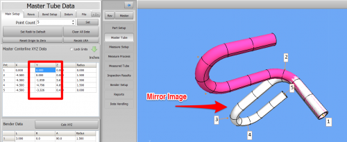
Creating a mirror image tube shape is very easy in VTube-STEP and VTube-LASER.
To create a mirror image part, use the Additive Inversion command on any entire column of XYZ values. This means that VTube will multiply an entire column of XYZ values by negative one.
|
 |
Learn the ODD/EVEN Rule for Mirror Image with Additive Inversion
ODD Rule: A mirror image is always the result with an ODD number of column additive inversions.
Any time the Additive Inversion feature is applied an odd number of times (1, 3, 5, etc.), the part will be a mirror image of the original.
EVEN Rule: A non-mirror image is always the result of an EVEN number of column additive inversions.
Any time this feature is applied an even number of times (2, 4, 6, etc.), the part will be the same shape, but with a different orientation in space.
Use these Steps for using Addition Inversion
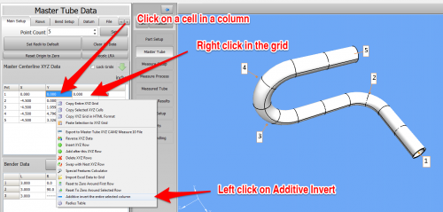
STEP 1: Additive Invert a Column in the XYZ Coordinates
|
Select a cell in an XYZ column to invert, right-click, and choose Additive Invert.
|
 |
STEP 2: Redraw and Zoom All
|
If the new part does not appear on the screen, then REDRAW and ZOOM ALL.
|
 |
METHOD 2: How to Create a Mirror Image Part - Swap Any Two Columns in an XYZ Grid
|
VTube also lets you perform column swaps. This means that VTube can swap the XY, XZ, or YZ columns in an XYZ grid.
Any time this feature is applied an even number of times (2, 4, 6, etc.), the part will be the same shape, but with a different orientation in space. |
 |
STEP 1: Swap Two XYZ Columns
| Select a cell in an - Mrr column to swap, then right-click and choose a swap option. | 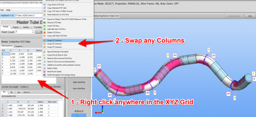 |
STEP 2: Redraw, Zoom All, and Alignment
|
If the new part does not appear on the screen, then REDRAW and ZOOM ALL. If multiple representations of the tube are switched on (like the ALIGNED and MASTER are on here), then you will see the before and after results after you perform an alignment. |
 |